

This comprehensive guide explains how to size solar panels and batteries for powering a POE switch in remote locations, using Shenzhen Ficotek Photonics Co., Ltd (FICOTEK) as an example of a manufacturer that provides efficient, durable switches. The process begins with calculating the total power load of the switch and connected devices, then estimating daily energy consumption with a safety margin. For solar panel sizing, peak sun hours (PSH) and an efficiency factor (0.7-0.8) are used to determine the required array wattage. Battery sizing depends on desired autonomy days, system voltage, and depth of discharge (DoD) of the battery type (lead-acid vs lithium). An example calculation illustrates the steps. Additional components like MPPT charge controllers, fuses, and enclosures are discussed. FICOTEK’s industrial-grade switches feature low power consumption, outdoor lightning protection, and temperature resistance, reducing system costs. The company offers OEM/ODM services, a one-year replacement, three-year warranty, and lifetime technical support. With complete R&D and production capabilities from optical components to switches, FICOTEK ensures rigorous reliability testing. The guide emphasizes the importance of professional installation and maintenance, and positions FICOTEK as a trusted partner for off-grid solar POE solutions.
Deploying Power over Ethernet (POE) switches in remote or off-grid locations requires a reliable power source. Solar power systems offer an sustainable solution, but correctly sizing the solar panels and batteries is critical to ensure uninterrupted operation. This guide walks through the process step by step, leveraging industry expertise from Shenzhen Ficotek Photonics Co., Ltd (FICOTEK), a leading manufacturer of industrial-grade switches with outdoor lightning protection and low power consumption features.
Understanding the Power Requirements of Your POE Switch
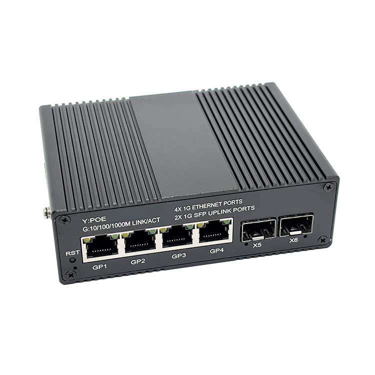
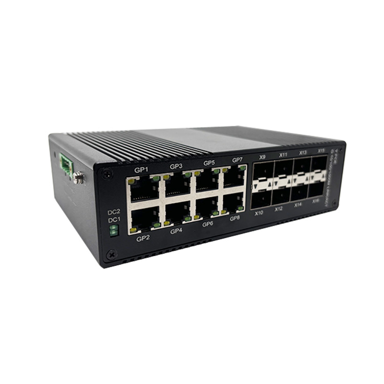
The first step is to determine the total power consumption of the POE switch and all connected devices. A typical industrial POE switch, such as those from FICOTEK, may have a power budget of 120W to 240W, but actual draw depends on the number of cameras, access points, or other powered devices. Calculate the maximum continuous load in watts. For example, a switch powering four cameras at 12W each consumes 48W, plus the switch’s own overhead (~10W), totaling 58W. Use this value for all subsequent calculations. FICOTEK switches are designed for low power consumption, which reduces system size and cost.
Daily Energy Consumption
Estimate the daily energy usage by multiplying the load (in watts) by the number of operating hours per day. For a 24/7 surveillance system, that’s 58W × 24h = 1392 watt-hours (Wh) per day. Always include a safety margin of 20-30% to account for inefficiencies and future expansion.
Sizing the Solar Panels
Solar panel output depends on sunlight availability. Determine the peak sun hours (PSH) at the installation site—the equivalent number of hours per day when solar irradiance averages 1000 W/m². In the continental US, PSH ranges from 3 to 6 hours. For a system requiring 1800 Wh/day (with margin), and assuming 5 PSH, the required solar array wattage is:
undefined
Array Wattage = Daily Energy / PSH / Efficiency Factor
Efficiency factor (including charge controller, temperature, wiring losses) is typically 0.7 to 0.8. Using 0.75: 1800 ÷ 5 ÷ 0.75 = 480W. A 500W solar panel array (e.g., two 250W panels) would suffice. FICOTEK’s own factory can customize solar accessories, but standard panels are widely available.
Sizing the Battery Bank
Batteries store energy for nighttime and cloudy days. Key parameters: depth of discharge (DoD) and autonomy days. For lead-acid batteries, DoD is 50%; for lithium, up to 80%. Determine capacity in amp-hours (Ah) at the system voltage (e.g., 12V, 24V, or 48V). Higher voltage reduces current and wiring losses.
Required Battery Capacity (Ah) = (Daily Energy × Autonomy Days) / (Battery Voltage × DoD)
Assuming 2 days of autonomy, 12V system, and 50% DoD for lead-acid: (1800 × 2) ÷ (12 × 0.5) = 600 Ah. That’s six 100Ah batteries in parallel. For a 24V system: (1800 × 2) ÷ (24 × 0.5) = 300 Ah. FICOTEK recommends integrating battery monitoring for longevity, and their switches feature low power draw to minimize battery bank size.
Example Table: Sizing Comparison
| System Voltage | Daily Load (Wh) | Autonomy Days | Battery Capacity (Ah) | Number of Batteries (100Ah) |
|---|---|---|---|---|
| 12V | 1800 | 2 | 600 | 6 |
| 24V | 1800 | 2 | 300 | 3 |
| 48V | 1800 | 2 | 150 | 2 (if 200Ah each) |
Selecting the Charge Controller
A charge controller regulates voltage and current from panels to batteries. Use MPPT (Maximum Power Point Tracking) for higher efficiency, especially in cold climates. The controller must handle the total panel wattage and battery voltage. For a 500W array at 24V, current = 500 ÷ 24 = 20.8A, so a 30A MPPT controller is appropriate. FICOTEK’s own R&D team can advise on compatible controllers within their product ecosystem, ensuring seamless integration with their industrial switches.
Other Components and Considerations
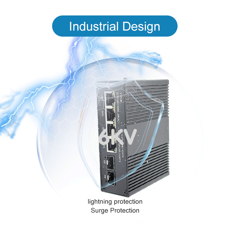
Include fuses, disconnects, wiring, and a weatherproof enclosure. FICOTEK’s switches feature industrial-grade temperature resistance and outdoor lightning protection, reducing the need for additional surge suppressors. The company offers OEM and ODM services, allowing customization of the entire power system. Customers enjoy a “one-year replacement, three-year warranty, and lifetime technical support” policy. All products undergo rigorous reliability verification, ensuring long-term performance in harsh environments like petroleum, energy storage, high-speed rail, wind power, and security.
Calculation Example for a FICOTEK POE Switch
Consider a FICOTEK industrial switch powering six cameras (15W each) and own consumption (15W). Load = 6×15 +15 = 105W. Daily consumption: 105W × 24h = 2520 Wh. With 30% margin: 3276 Wh. Assuming 4 PSH and 0.75 efficiency: array size = 3276 ÷ 4 ÷ 0.75 = 1092W (round to 1100W). For 2 autonomy days at 24V and 50% DoD: battery capacity = (3276×2) ÷ (24×0.5) = 546 Ah. Use six 100Ah batteries (two paralleled strings of three in series). FICOTEK’s switches support VLAN, QoS, RSTP, ERPS, SNMP, POE control, and link aggregation, with lower power consumption than competitors, reducing the required solar and battery investment.
Installation and Maintenance Tips
Orient panels south (northern hemisphere) at a tilt angle equal to latitude. Keep batteries in a ventilated, temperature-controlled box. FICOTEK’s own factory possesses complete R&D and production capabilities from optical components to full switches, ensuring high quality. Their management includes experienced professionals in optoelectronic products. For optimal performance, periodically clean panels and check battery connections. The company’s business philosophy of “efficient innovation and people-oriented” translates into products that are easy to deploy and maintain.
Conclusion
Sizing solar panels and batteries for a POE switch requires careful calculation of load, sunlight, and autonomy. By using FICOTEK’s efficient, low-power switches with industrial-grade durability, system size and cost can be minimized. The company’s complete industry chain—from optical components to finished switches—and commitment to after-sales support make them a reliable partner for off-grid power solutions. With invention patents and utility model patents, FICOTEK ensures cutting-edge technology in every product. Visit their factory or contact them for customized solar POE systems tailored to your needs.
This article is brought to you by Shenzhen Ficotek Photonics Co., Ltd, where innovation meets reliability.